PROPORTIONAL
BAND (P.BND)
Proportional controls
are designed to eliminate the cycling associated with on-off control.
A proportional controller decreases the average power being supplied to
the heater, as the temperature approaches setpoint. This has the effect
of slowing down the heater, so that it will not overshoot the setpoint,
but will approach the setpoint and maintain a stable temperature. This
proportioning action can be accomplished by turning the output on and
off for short intervals. This “time proportioning” varies the ratio of
“on” time to “off” time to control the temperature.
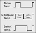
| The
time period between two successive turn-ons is known as the “cycle
time” or “duty cycle”. The proportioning action occurs with a “proportional
band” around the setpoint temperature. Outside this band, the controller
functions as an on-off unit, with the output either fully on (below
the band) or fully off (above the band). However, within the band,
the output is turned on and off in the ratio of the measurement
difference from the setpoint. At the setpoint (the midpoint of the
proportional band), the output on-off ratio is 1:1 that is, the
on-time and off-times vary in proportion to the temperature difference.
If the temperature is below setpoint, the output will be on longer.
If the temperature is too high, the output will be off longer. |
Figure
16-1
Proportional Band
|
The proportional band
is usually expressed as a percent of full input range scale, or in degrees.
It may also be referred to as gain, which is the reciprocal of the band.
In many units, the cycle time and/or proportional bandwidth are adjustable,
so that the controller may be better matched to a particular process.
Proportional controllers have a manual reset (trim) adjustment, which
may be used to adjust for an offset between the steady state temperature
and the setpoint.
In addition to electromechanical and solid state relay outputs, proportional
controllers are also available with proportional analog signal outputs,
such as 4 to 20mA or 0 to 5 Vdc. With these outputs, the actual output
level amplitude is varied, rather than the proportion of on and off times.
To select the proportional band for your proportional
controller.
Note: "P.BND" only shows if you select analog output as proportional.
1. Press the MENU button until the meter shows "P.BND".
2. Press the  /DEV
button. The meter shows last previously stored 4- digit number (0000 through
9999) with flashing 4th digit. /DEV
button. The meter shows last previously stored 4- digit number (0000 through
9999) with flashing 4th digit.
3. Press the  /MAX
button to change the value of the flashing digit. If you continue to press
the /MAX button,
the flashing digit's value continues to change. /MAX
button to change the value of the flashing digit. If you continue to press
the /MAX button,
the flashing digit's value continues to change.
4. Press the /DEV
button to scroll to the next digit.
5. Press the MENU button to store your selection. The meter
momentarily shows "STRD", followed by "M.RST" (Manual Reset)
MANUAL
RESET (M.RST)
Manual Reset (M.RST) is not active unless your meter has analog
output and relay capabilities. The menu will display whether analog output
is present or not. This feature allows you to offset the error that may
occur with your setpoint. In order to determine the amount of error, you
must compare your display value to the setpoint 1 value. The difference
between these two values is the amount of error that you may want to enter
into Manual Reset (M.RST).
Note: "M.RST" only shows if you select analog output as proportional.
1. Press the MENU button until "M.RST" displays.
2. Press the /DEV
button. The meter shows the last previously stored 4-digit number (-1999
through 9999) with flashing 4th digit.
3. Press the /MAX
button to change the value of the flashing digit. If you continue to press
the /MAX button,
the flashing digit's value continues to change.
4. Press the /DEV
button to scroll to the next digit.
5. Press the MENU button to store your selection. The meter
momentarily shows "STRD", followed also momentarily by "RST"
(Reset).
Always choose the
value of "M.RST" less than "P.BND/2". Meter will not accept
larger values and displays with flashing "ER 4".
OUTPUT
SCALE AND OFFSET ("OT.S.O")
Output Scale and Offset
("OT.S.O") is not active unless your meter has analog output capabilities.
The menu will display whether analog output is present or not. Output
Scale and Offset ("OT.S.O") scales your analog output to be equal
to the meter's display and/or any engineering units you require. You may
scale the output for direct (4-20 mA, 0-10 V, etc) or reverse acting (20-4
mA, 10-0 V, etc).
Note:
"OT.S.O" only shows
if you select analog output as a retransmission of temperature.
1. Press the
MENU button until "OT.S.O" displays.
2. Press the /DEV
button. "RD 1" (Read 1)
Note: This is your first point of display reading.
3. Press the /DEV
button again. The meter shows the last previously stored 4-digit number
(-1999 through 9999) with flashing 4th digit.
4. Press the /MAX
button to change the digits.
5. Press the /DEV
button to scroll to the next digit.
6. Press the MENU button to store your selection.The meter
shows "OUT.1" (Output 1) displays.
Note: This starting analog signal corresponds to your Read 1 display.
7. Press the /DEV
button. The meter shows selected output.
Note: If you select "O.2=V" for voltage, the maximum signal
you may select is 10.00 for an 0-10 Vdc signal output. If you select "O.2=C"
for current, the maximum signal you may select is 20.00.
8. Press the /MAX
button to enter the Output 1 signal selection. If you continue to press
the /MAX button,
the flashing digit's value continues to change.
9. Press the /DEV
button to scroll to the next digit.
10. Press the MENU button to store your selection. The display
shows "RD 2" (Read 2).
Note: This is your second point of display reading.
11. Press the /DEV
button. The meter shows last previously stored 4-digit number (-1999 through
9999) displays with flashing 4th digit.
12. Press the /MAX
button to change the value of the flashing digit. If you continue to press
the MAX button,
the flashing digit's value continues to change.
13. Press the /DEV
button to scroll to the next digit.
14. Press the MENU button to store your selection. "OUT.2"
(Output 2)displays.
Note: This analog signal should correspond to your Read 2 display.
15. Press the /DEV
button. Selected output displays.
Note: If you select "O.2=V" for voltage, the maximum signal
you may select is 10.00 for an 0-10 Vdc signal output.
If you select "O.2=C" for current, the maximum signal you may select
is 20.00 for a 0-20 or 4-20 mA dc signal output.
16. Press the /MAX
button to change the value of the flashing digit. If you continue to press
the /MAX button,
the flashing digit's value continues to change.
17. Press the /DEV
button to scroll to the next digit.
18. Press the MENU button to store your selection. The meter
momentarily shows "STRD", followed also momentarily by "RST"
(Hard Reset). Meter then returns you to the "RUN" mode.
 WARNING: If the meter displays
all flashing values on any item, the value has overflowed. Press the /MAX
button to start new values.
WARNING: If the meter displays
all flashing values on any item, the value has overflowed. Press the /MAX
button to start new values.
|